The 48 V/12 V Automotive Evaluation Power Modules (EPC9137, EPC9163, EPC9165) Utilize the Two-Phase Synchronous Buck/Boost Topology
GaN Talk – Yuanzhe Zhang
Feb 11, 2022
Introduction
The 48 V/12 V automotive evaluation power modules (EPC9137, EPC9163, EPC9165, etc) utilize the two-phase synchronous buck/boost topology. The edge connectors and controller card are also designed to operate two modules in parallel with one controller, effectively achieving four-phase and therefore double the rated current and power. An example using EPC9137 modules are shown in Figure 1.
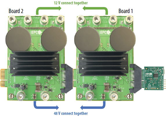 Figure 1. Two EPC9137s connected in parallel to achieve 3 kW (12 V 250 A) output using one EPC9528 controller.
Connection
The difference between this two-board configuration and a four-phase converter is the 12 V connection impedance. Ideally, this impedance should be extremely low to achieve inductor current ripple cancelation. Therefore, the 12 V (low voltage) should be connected using a bus bar, or 8 AWG short wires to ensure low impedance, as illustrated in Figure 2. The connection for 48 V (high voltage) bus is less critical. But low impedance is still preferred to avoid parasitic resonance. Ground wires (GND) should also be paired with the corresponding bus and avoid ground loops.
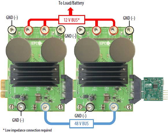 Figure 2. Two EPC9137s connected in parallel with one EPC9528 controller, showing 48 V bus and 12 V bus connections. The 12 V bus requires low impedance between the boards.
Sensing and PWM
Sensing and PWM signals are routed through the edge connectors, as shown in Figure. 3. Make sure to remove any jumper on J800 on both boards. The 3.3 V for the controller is only provided by Board 1. Each board generates its own 5 V supply. Due to the pin limits on the edge connector, only 2-board parallel is supported. The phase shift of the PWM signals is modified to ensure proper ripple cancelation: PWM1 and 2 are 180 degrees out of phase, so as for PWM3 and 4, and 90 degrees phase shift is between PWM 1 and 3.
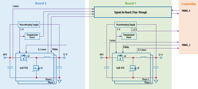 Figure 3. Block diagram of the two boards connected with one controller.
Control
Average current mode control with out-of-band current balancing is used. A simplified control diagram is shown in Figure 4. The outer voltage loop generates the current reference IREF for phase 1 inductor average current IL1. The remaining phase inductor currents IL2, IL3, IL4 are sensed and compared to IL1. If there is any imbalance, a duty cycle offset Δd for each phase is generated to minimize the imbalance. This happens at a much lower frequency compared to the main control loop, usually at 10 kHz.
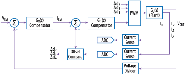 Figure 4. Control diagram of the average current mode control loop
Thermal
Due to the direction of heatsink fins, the board downwind will receive reduced airflow for cooling. A minimum of 2000 LFM is required when operating close to rated power. The actual output power may be less than the sum of two individual boards due to inadequate cooling.
Experimental Results
Figure 5 shows the measured efficiency and loss for two EPC9137 boards operating at 48 V input and 12 V output. Figure 6 shows the corresponding thermal image at full load (12 V, 250 A output). Due to the airflow direction, the board placed downwind is hotter.
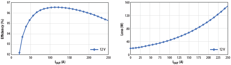 Figure 5. Measured efficiency and loss for two EPC9137s connected in parallel. VIN = 48 V, VOUT = 12 V, f = 250 kHz.
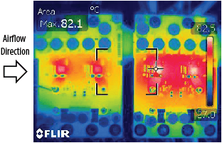 Figure 6. Example thermal image of two EPC9137s. VIN = 48 V, VOUT = 12 V, IOUT = 250 A, f = 250 kHz. Downwind board is hotter
Summary
The 48 V/12 V automotive evaluation power modules are designed to be parallel to achieve double the rated power, when properly cooled. Detailed connection diagram, control method as well as current balancing are given. An example system with two EPC9137s and one EPC9528 is tested at 3 kW output when converting 48 V to 12 V.