How to Design a 12 V to 48 V / 500 W 2-Phase Boost Converter Using eGaN FETs and the Renesas ISL81807 Controller with Same BOM Size as Silicon, Offering Superior Efficiency and Power Density
技术分享GaN技术杂谈 – Jianglin Zhu
1月 07, 2022
48 V is being adopted in many applications, including AI systems, data centers, and mild hybrid electric vehicles. However, the conventional 12 V ecosystem is still dominant, so a high power density 12 V to 48 V boost converter is required. The fast-switching speed and low RDS(on) of eGaN® FETs can help address this challenge. In this post, the design of a 12 V to 48 V, 500 W DC-DC power module using eGaN FETs directly driven by eGaN FET compatible ISL81807 controller IC from Renesas in the simple and low-cost synchronous boost topology is evaluated.
Design of a 2-phase eGaN FET-based synchronous boost converter
The multi-phase synchronous boost topology, shown in Figure 1, is popular in DC-DC step-up converter design for its simplicity, ease in control, and low cost.
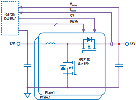 Figure 1: Simplified schematic block diagram of the EPC9166 eGaN FET-based synchronous boost converter
In this design, the 100 V rated EPC2218 with RDS(on) of 3 mΩ is selected for the 12 V to 48 V, 500 W power stage. The ISL81807 is an 80 V boost controller that can drive eGaN FET directly. Compared to a digital controller solution, the analog controller solution does not need the driver IC, current sense IC, housekeeping power IC, and thus dramatically reduces complexity and Bill of Material (BOM) count. The controller employs current mode control with full protection features such as UVLO and over-current protection. The ISL81807 also allows the designer to choose between constant current mode (CCM) or diode emulation to improve light-load efficiency. The converter's switching frequency is set at 500 kHz, and a 2 μH inductor (SER2011-202 Coilcraft) with 1.3 mΩ DCR and 37 A saturation current is chosen.
Design Validation
The EPC9166 synchronous boost converter is shown in Figure 2. The switch-node voltage v SW waveform at 5 A output current is shown in Figure 3; the switching is seen to be fast and clean. The overall power efficiency and power loss of the synchronous boost converter are shown in Figure 4, with a peak efficiency of 96.6% at 12 V input and 48 V output.
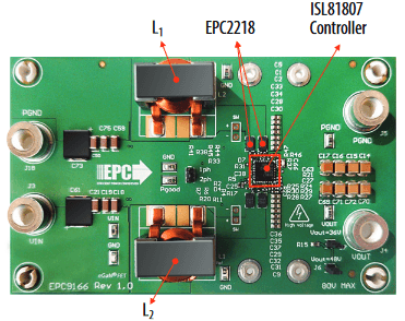 Figure 2: Photo of the EPC9166 synchronous boost converter designed for 12 V to 60 V, 500 W operation
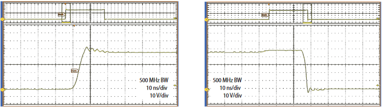 Figure 3: Switch-node voltage vSW waveform at 5 A output current.
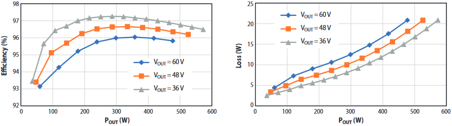 Figure 4: Total system efficiency and loss of the EPC9166 operating at 12 V input and various output voltages.
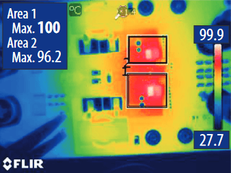
Thermal Performance
The thermal image of the converter operating at 12 V to 48 V, 10 A output current with moderate cooling (around 400 LFM forced air cooling) is shown in Figure 5. A temperature rise of 72 °C is observed. The board can deliver 480 W power without a heatsink.
Conclusion
The EPC9166, an eGaN FET-based 2-phase synchronous boost converter designed around the ISL81807 controller, is introduced. At 12 V input and 48 V output, it can deliver 500 W and achieves 96.6% peak efficiency and 72°C temperature rise with moderate cooling. The whole solution comprises four eGaN FETS with a total die size of only 27.3 mm2. The introduction of eGaN compatible IC ISL81807 can drive eGaN FETs directly by integrating the gate drivers, controller, housekeeping power, and current sense amplifier function in a single chip, which significantly reduced the complexity and cost.