When the Inverter Moves Inside the Actuator: EPC91132 in Humanoid Joint and Drone Motor Drives
GaN Talk – Maurizio Di Paolo Emilio
Sep 02, 2026
Qian Luo, Author, WBG TechnoBite
In humanoid robot wrists and dexterous hands, as well as compact drone propulsion systems, motor drives are moving from external controller boards into the actuator itself. At that point, the inverter is no longer an independent unit that simply delivers three-phase current to the motor; it must share a tightly constrained space with the motor, position sensor, mechanical structure, and thermal path.
This changes the design priorities for compact motor drives. Continuous current and torque capability certainly depend on the power devices, but where the DC-link capacitors can be placed, whether heat can be transferred into the housing or airflow, and how sensing and protection signals are routed all shape the final system performance.
EPC91132 is EPC's three-phase BLDC motor-drive reference design for this use case. Built around the EPC33110 three-phase GaN module, it supports a 10–60 V input range and integrates an MCU, regulated power supplies, DC-bus voltage sensing, current sensing and overcurrent protection, an onboard magnetic encoder, and RS-485 communications. The current-sensor ICs provide an embedded fault signal set to 30 A; the board can be programmed through a dedicated connector and monitored in real time over RS-485.
EPC33110 integrates three GaN half-bridges, gate drivers, bootstrap circuitry, and level shifters in a 6 mm × 6.5 mm QFN package. The module operates from a single 5 V supply and can operate up to 80 V (100 V absolute maximum input), supports 3.3 V or 5 V logic interfaces, and has a typical on-resistance of 11.7 mΩ. With the outer ring retained, the board can be installed in a Lingkong MG8008E-i9 humanoid joint motor; removing the ring reduces the core inverter board to 23 mm in diameter for use with Vertiq 23-06 drone motors.
Figure 1. (a) Overview of the EPC91132 board — a three-phase inverter for drone and humanoid joint motors. Source: EPC.
The value of this reference design is not simply that it makes the three-phase inverter smaller. It demonstrates how the mechanical envelope, local energy storage, thermal conditions, and control chain need to be considered together once the drive is actually embedded in the actuator.
What Design Assumptions Change First Once the Inverter Moves Inside the Motor?
Small motors typically have low inductance and low resistance. Higher switching frequency helps improve current-regulation bandwidth and dynamic response, but once the inverter moves inside the motor housing, engineers must consider more than switching frequency and device losses; the power loop, thermal interface, and DC-bus energy storage also need to be reassessed.
|
|
Author: In EPC91132's public introduction materials, the target motors are low-inductance, low-resistance machines, where high switching frequency helps improve current-regulation bandwidth and dynamic response. When the inverter moves from a separate controller board into the motor housing, which design assumptions need to change first for robotics and UAV teams?
|
|
EPC:
Placing the inverter inside the motor can reduce EMI generated by the motor phase leads; positioning it close to the housing also helps spread the generated heat. However, integrating the inverter into the motor reduces the amount of capacitance that can be accommodated, so the distributed DC bus fluctuates more than it does when the drive board is located outside the motor. According to EPC, the devices' 100 V withstand capability is not a primary limiting factor in the bus-fluctuation assessment for this reference design.
|
|
This answer reveals the two-sided nature of an embedded drive. Shorter phase leads and closer proximity to the housing create new opportunities to optimize EMI and heat spreading; at the same time, the available space for DC-link capacitors is compressed. For a compact GaN drive, the mechanical envelope is no longer just an assembly constraint — it becomes part of the power loop.
For teams that need to implement a three-phase drive in a tightly constrained space, this integration is about more than shrinking the package. By bringing the three-phase power switches, gate drivers, and level shifters into one module, the external design no longer needs a repeated discrete gate-drive circuit for each phase, reducing component count and the number of PCB-layout-sensitive points. EPC91132 then places local energy storage, sensing, protection, and control functions into the same actuator space, providing a system-level starting point that engineering teams can continue to optimize.
Which Functions Need to Stay Close to the Power Stage?
Layout inside the actuator cannot be partitioned solely according to the schematic. The distance from the DC-link capacitors to the power stage, from the analog sensing circuits to the MCU, and whether the position sensor remains inside the motor all affect bus transients, protection response, and control quality.
|
|
Author: In addition to the EPC33110 power module, EPC91132 integrates an MCU, regulated power supplies, DC-bus sensing, current sensing and overcurrent protection, an onboard magnetic encoder, and RS-485 communications. In an embedded drive, which functions most need to remain physically close to the power stage? What system-level penalty appears if they are moved back to an external controller board?
|
|
EPC:
The motor rotor position sensor must, in any case, be located inside the motor. The DC-bus capacitors must be kept as close to the power stage as possible. Depending on the current-sensing scheme, the current sensing may also need to be close to the power module. Overcurrent detection must be located close to the current sensors. The MCU must be close to the analog sensing circuits, including current and voltage sensing.
|
|
This defines a clear layout priority for compact motor drives. The position sensor provides the basis for commutation; the DC-link capacitors provide local energy storage and influence bus transients; current sensing and overcurrent protection determine the response under abnormal conditions; and the distance between the MCU and the analog sensing circuits affects whether signals remain trustworthy in a high-speed switching environment.
Moving these functions farther away does more than increase wiring length. Parasitics, noise coupling, protection delay, and interface complexity all become part of the system-validation scope. In a multi-joint humanoid robot, the issue extends further to encoders, communications, and coordinated operation of multiple motors.
How Can One Board Fit Two Actuator Envelopes?
EPC91132's breakout-ring structure illustrates one mechanical-design approach for compact drives: with the outer ring retained, the board can be installed in a Lingkong MG8008E-i9 humanoid joint motor; once the ring is removed, the core inverter board is reduced to 23 mm in diameter for use with compact drone motors such as the Vertiq 23-06.
Figure 2. (a) EPC91132 with the outer PCB ring installed in a humanoid joint motor. Source: EPC.
|
|
Author: By retaining or removing the outer ring, EPC91132 can be adapted to both a humanoid joint motor and a 23 mm drone motor. When one inverter design must fit two actuator envelopes, what are the most important engineering trade-offs? Which parts of this approach can be transferred to other compact motors?
|
|
EPC:
The smallest motor dictates the entire design. Engineers need to recognize that connectors are the first components to be removed. Expanding the board dimensions from the smallest version is relatively straightforward; the real challenge is fitting everything into the smallest dimensions. EPC91132 was designed to give designers a good, optimizable starting point from which they can develop their own systems.
|
|
“The smallest motor dictates the entire design” is the core principle behind this structure. Larger actuators can extend the board and interfaces outward, but whether the smallest envelope can simultaneously accommodate the power stage, DC link, current sensing, encoder, control, and communications determines whether the overall architecture is viable.
The breakout ring is therefore not a final product form factor, but a reference design that can be trimmed and extended. It allows engineering teams to start from a validated core area and then optimize it for the housing, interfaces, and assembly method of the target motor.
Why Does the Same Power Platform Show Two Different Thermal Behaviors?
The most noteworthy aspect of EPC91132's testing is not simply that it was installed in two different motors, but that the same power platform was placed within two very different thermal boundaries.
In the humanoid-joint test, the system used a 48 V input and operated at 60/80/100 kHz PWM with a 20 ns dead time. The test motor ran at 100 RPM without forced-air cooling. Tests were performed both without the motor cover and with the motor cover acting as a heatsink for the module. At 11 ARMS continuous phase current, the temperature rise was approximately 70 °C, and the system reached thermal equilibrium after about 10 minutes. For the test motor, which had a torque constant of 2 Nm/ARMS, the 22 Nm maximum load corresponded to 11 ARMS in each inverter leg. The official product page and current datasheet further state that, with the board placed inside the motor housing, the EPC33110 can deliver pulsed output up to 21 Apk (15 ARMS). This figure defines pulsed capability and must be distinguished from the 11 ARMS continuous test value above; it should not be interpreted as a continuous-current rating.
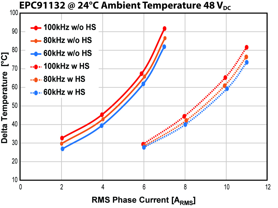
Figure 3. Output-current capability of EPC33110 in a humanoid robot joint. DcBus = 48 V; PWM frequency = 60, 80, 100 kHz; without (left) and with (right) the motor cover used as a heatsink for the module. Source: EPC.
The boundary conditions are different for the drone. A Vertiq 23-06 220KV motor equipped with a 12-inch underactuated propeller was operated from a 24 V input at 100 kHz PWM with a 20 ns dead time, over a speed range of 1000–3400 RPM. Airflow generated by the propeller provides forced convection; at an ambient temperature of approximately 26 °C, the maximum recorded temperature rise was about 4 °C.
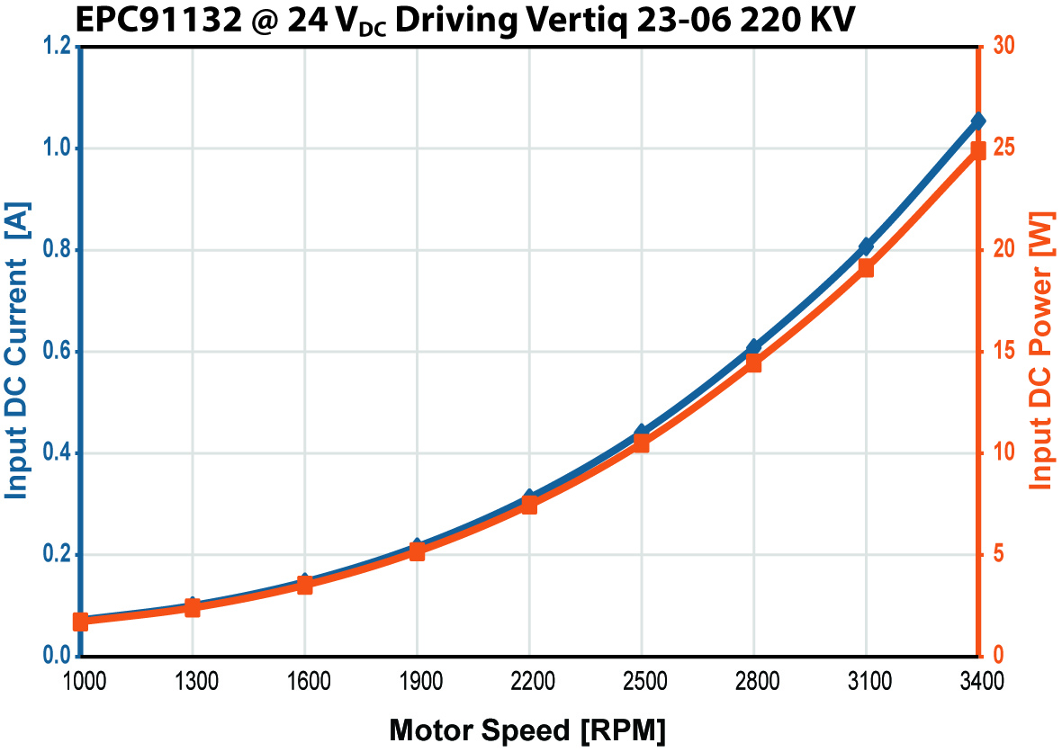
Figure 4. Input DC current and power versus motor speed while the motor maintains the torque required by the propeller. Source: EPC.
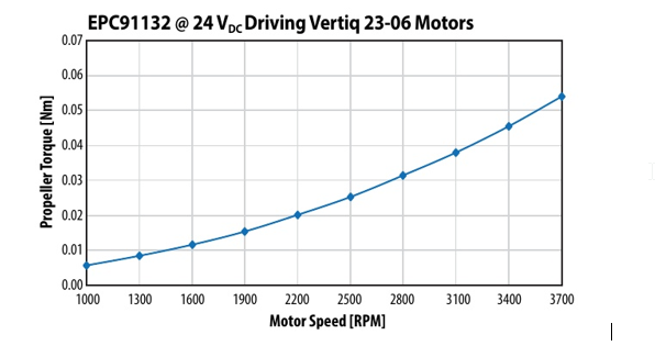
Figure 5. Propeller torque versus motor speed. Source: EPC.
|
Test condition
|
Humanoid joint motor
|
Drone motor
|
|
Motor / load
|
Lingkong MG8008E-i9
|
Vertiq 23-06 220KV + 12-inch underactuated propeller
|
|
Input & PWM
|
48 V; 60 / 80 / 100 kHz; 20 ns
|
24 V; 100 kHz; 20 ns
|
|
Thermal condition
|
No forced-air cooling; tested both without the motor cover and with the motor cover used as a heatsink
|
Propeller airflow provides forced convection
|
|
Key test result
|
11 ARMS continuous phase current; approx. 70 °C temperature rise; thermal equilibrium after approx. 10 minutes
|
Maximum temperature rise approx. 4 °C at approx. 26 °C ambient
|
|
|
Author: The same EPC91132 platform was tested in a humanoid joint under natural convection and in a drone motor with propeller airflow. How should engineers interpret this difference when estimating continuous current and torque capability for compact GaN motor drives?
|
|
EPC:
The way a power module operates depends on the thermal conditions. EPC91132 can therefore be used in two completely different environments and show different capabilities. Humanoid robots do not have an efficient heat-removal path, so the same power module can deliver less current than in a drone application, where stronger forced-air convection is available. Engineers should assess their system's ability to remove heat and use EPC's qSG document to evaluate the capabilities of EPC33110 and EPC91132.
|
|
The significance of the two data sets is not to place humanoid robots and drones on the same performance scale. Rather, they show that continuous current must be defined together with the motor, housing, mounting method, speed, and cooling conditions. The original test material provides a current-versus-temperature-rise curve for the humanoid joint, and relationships among input DC current/power, speed, and propeller torque for the drone motor. Together, these plots form the evidence needed to understand the two thermal boundaries, rather than serving as isolated temperature-rise numbers. In the humanoid joint, heat must leave the system through the motor housing and natural convection; in the drone, propeller airflow directly changes the steady-state thermal balance.
The continuous capability of the same power module ultimately depends on whether heat can be removed from the actuator in a stable way, rather than being determined by any single rated-current figure.
What Should Be Validated First When Moving from Reference Design to Product?
EPC91132 provides a system-level starting point for compact actuators, but a reference design is not a final answer that can be copied directly into every motor. The target motor, housing structure, cooling conditions, and mission profile differ from one application to another, and so do the validation priorities.
|
|
Author: If an engineering team wants to move from evaluating EPC91132 to developing its own embedded GaN motor drive, what validation data should it collect for the target motor, housing, and cooling conditions before committing to the architecture — thermal equilibrium, continuous and pulsed current, torque ripple, sensing accuracy, EMI, communication robustness, or other metrics? Which item is most often underestimated?
|
|
EPC:
It depends on the final application. Humanoid-robot designers often underestimate electromagnetic compatibility. When multiple motors operate together in a kinematic chain, they can sometimes create problems for digital communication protocols. For a humanoid robot, pulsed operation is important because it represents the robot's typical mission profile; for a drone, steady-state operation is more representative. Heat-transfer assessment is the starting point; from there, the team can determine how much current the final system will be able to process.
|
|
This answer provides a clear validation sequence. Heat-transfer capability needs to be established first; then, based on the target application, the test boundaries for continuous and pulsed current can be defined. A humanoid robot cannot rely on a single steady-state thermal test: validation should also cover the pulsed mission profile of the joints and EMC under conditions where multiple motors, encoders, and digital communications coexist. For drones, the focus should be on the relationship among sustained speed, input power, propeller torque, and steady-state temperature rise.
Closing Note
The significance of EPC91132 is not simply that a GaN inverter can be reduced to 23 mm. It brings the real constraints of a compact actuator into one design: the power stage must fit inside a limited envelope, the DC link and sensing chain must maintain appropriate physical proximity, heat must leave the system through the housing or airflow, and EMI and communications in a multi-motor environment must also be validated.
Once the inverter moves inside the actuator, the design unit is no longer just a drive board, but the complete system of “power stage + motor + structure + thermal path + control.” EPC33110's three-phase GaN integration provides the basis for miniaturization; the mission profile, thermal design, and system-level coordination determine whether it can operate continuously and reliably in the target product.
Sources
- EPC91132 product page and evaluation-board datasheet, Efficient Power Conversion (EPC)
- EPC91132: the smallest motor reference design based on EPC33110 GaN three-phase QFN module, Marco Palma and Simone Scano, EPC
- GaN-Based Motor Drive Architecture for Robotics and UAV Applications, Maurizio Di Paolo Emilio
- Three-Phase Module Based on Monolithic GaN Half-Bridge ICs, Federico Unnia and Marco Palma, Bodo's Power Systems, December 2025, pp. 24–26
- Test motor documentation: LKMTECH MG8008-i9v3; Vertiq 23-06 G1 Module
- All images and test data in this article were provided by EPC; the technical Q&A is based on an interview with EPC's technical team.
Tags: