eGaN FETs Are Low EMI Solutions!
GaN Talk – Michael de Rooij, Ph.D.
May 19, 2020
GaN FETs can switch significantly faster than Si MOSFETs causing many system designers to ask − how does higher switching speeds impact EMI?
This blog discusses simple mitigation techniques for consideration when designing switching converter systems using eGaN® FETs and will show why GaN FETs generate less EMI than MOSFETs, despite their fast-switching speeds.
Overview of an EMI System
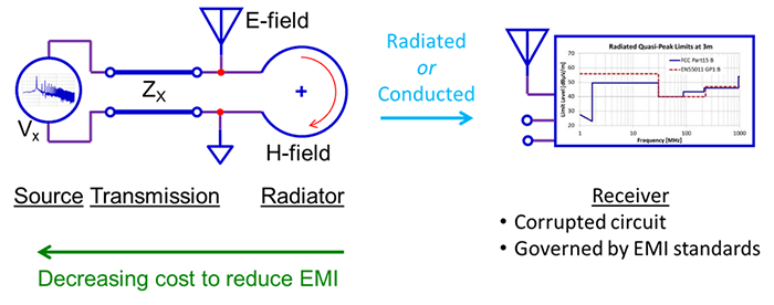
 Figure 1: Overview of an EMI system
Figure 1 shows the components of an EMI system:
The first component of an EMI system is the energy source, which can originate in various forms, for example as a switching event of a transistor. Energy from the source needs a transmission path such as conductors on a PCB. These transmission paths can form plates of a capacitor where the voltage can radiate as an E-field or in loops where the current path can radiate as an H-field. It is further possible for a loop to radiate an E-field and, vice versa, for the capacitor plates to radiate H-fields.
Regardless of transmission means and path, the EMI energy must be received. In the case of direct transmission, it is termed ‘conducted EMI’, and in the case of fields it is termed ‘radiation’.
The final component in an EMI system is the receiver which, by definition, is a circuit that becomes corrupted and results in undesirable behavior. The receiver circuit can be the same circuit that includes the source or a 3rd party circuit, for example, a radio receiver. In the case of 3rd party receiver circuits, the prevention of EMI-induced undesirable behavior is governed by EMI standards.
Addressing EMI mitigation measures for compliance and corruption prevention inevitably adds cost to a system. The closer to (and including) the source that steps are taken to address EMI, the lower the cost to the system.
The Effect of Layout
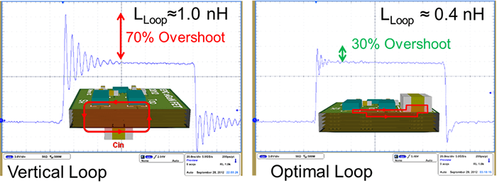
Layout is a zero-cost adder EMI mitigation measure. When designing converters, the layout inherently has parasitic inductance. In the synchronous buck converter example shown in figure 2, the effect of the loop inductance on the voltage overshoot of the switch-node following a rising edge hard-switching transition is shown.
The left image shows a layout with a loop inductance of approximately 1 nH and results in a 70% peak voltage overshoot with ringing. The right-side image shows a layout with a loop inductance of 400 pH and results in a 30% peak voltage overshoot with ringing.
 Figure 2: Effect of layout on overshoot
The EMI generated is proportional to the square of the voltage overshoot magnitude and typically propagates as an E-field emanating from the conductors that form capacitors with ground. The loop inductance also conducts a current during the ringing period with corresponding EMI generated that is proportional to the square of the current magnitude, which typically propagates as an H-field emanating from the power loop circuit.
Reducing the power loop inductance by half reduces the EMI generated by a factor of four.
The Effect of Rise/Fall Time
Even though GaN FETs can switch much faster than MOSFETs, it is important to note that there is fundamentally no change in EMI energy simply because one device switches faster than another. There is only a shift in spectral content.
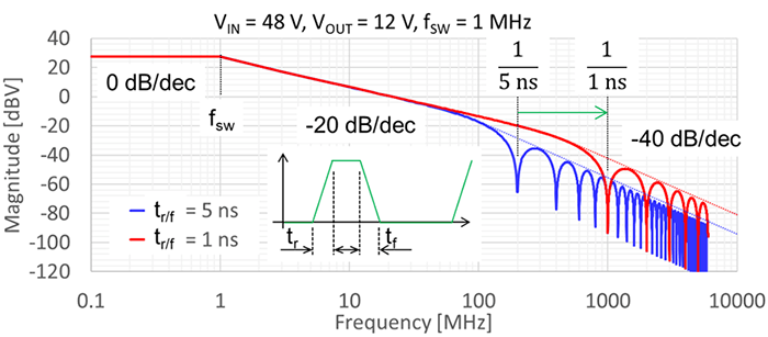
This is shown by example in figure 3 using a buck converter operating at 1 MHz, converting a 48 V input voltage to 12 V, for two switching transient conditions of 5 ns and 1 ns respectively. The graph shows the spectrum of the switch-node voltage for both transient conditions with the rising edge time set the same as the falling edge time and excludes voltage overshoot and ringing.
 Figure 3: Effect of spectral contect due to Rise/Fall time
At 90 MHz, the spectral content has already been attenuated by 42 dB. In the 5 ns transient case, the first frequency of note is 200 MHz or 1 over 5 ns, and in the 1 ns transient case, the first frequency of note is 1 GHz or 1 over 1 ns.
The rate of decrease in spectral magnitude above these frequencies is 40 dB per decade, which means that filtering requirements are already very low, thus making it more critical to address the voltage overshoot ringing discussed earlier.
The switch-node effectively forms the plate of a capacitor with the ground being the second plate, making this form of EMI E-field radiant dominant.
The Effect of Reverse Recovery (QRR)
Lastly, as an example, the often-overlooked impact of reverse recovery on EMI using a hard-switching buck converter is evaluated.
Reverse recovery manifests as a shoot-through current in the power loop and, as was discussed earlier, a current in the power loop leads to voltage overshoot and ringing. The reverse recovery adds to the energy in the power loop and, thus, adds energy to the EMI noise source that is proportional to the square of the reverse recovery current. This reverse recovery current can be several times higher in magnitude than the inductor current of the buck converter.
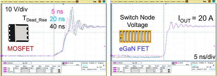
 Figure 4: Effect of reverse recovery (QRR)
The left waveform of figure 4 shows the voltage overshoot and ringing for a MOSFET-based buck converter with dead times of 5 ns, 20 ns and 40 ns respectively, and the eGaN FET equivalent on the right waveform under the same operating conditions.
It can be seen on the right waveform that a change in dead time has no effect on the eGaN FET because it has zero reverse recovery.
Summary
eGaN FETs and ICs are EMI compatible. By adopting simple layout techniques, one can ensure significant reduction in EMI generation that adds zero cost to EMI mitigation.
The higher switching slew rates only result in a shift in spectral content but do not increase EMI energy. At higher frequencies, EMI reduction techniques are more effective resulting in lower cost to implement.
Finally, eGaN FETs and ICs come in wafer-level chip scale packages (WLCS) that have virtually zero internal inductance and, additionally have zero reverse recovery and, thus, inherently generate less EMI energy in hard-switching converters.
Despite their significantly faster switching speeds, eGaN FETs generate less EMI than MOSFETs.
Note: For more information, including a detailed discussion from Würth Elektronik on the impact of inductor choice and placement, please see the video in our How to GaN series: Design Basics: EMI Mitigation Techniques.