Why you shouldn’t use Rds(on) to select and compare devices in switching power converters
GaN Talk – Andrea Gorgerino
Aug 05, 2023
Together with the voltage class, RDS(ON) is an ubiquitous parameter commonly used to describe Si MOSFET as well as GaN FETs. RDS(ON) is a good indicator of the size of the device within a given technology platform and, consequently, of its cost. However, in most switching power converters, losses are a combination of conduction losses and switching losses. Therefore, RDS(ON) is not a reliable indicator of performance either between different technology platforms or even within the same technology platform. This is particularly true when designers are transitioning from Si MOSFET to GaN FETs.
Si MOSFETs and GaN FETs have very different trade-offs in parameters due to their fundamental device characteristics. Comparing them is further complicated by a general lack of tools that can easily compare devices from different manufacturers. In response to this challenge, EPC has partnered with DiscoverEE. to release a silicon vs. eGan FETs cross reference tool based on a database of over 20,000 Si MOSFET and GaN FETs. As an example, by using the default conditions of the tool, users can search for alternatives to the ONSemi FDMS2D5N08C, an 80V 2.2mO device. This tool relies on simplified models derived from the datasheet tables and calculates an equivalent figure of merit in a given set of default conditions, expressed in Watts. Figure 1 shows the results of this search revealing that all the GaN FETs shown have higher RDS(ON) but a better power loss figure of merit.
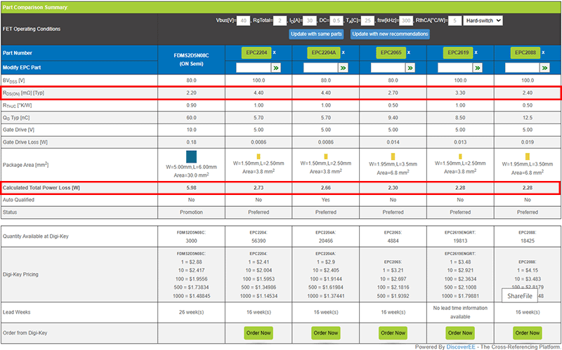 Figure 1 - Cross reference results for ONSemi FDMS2D5N08C
To validate this choice, users can use this Buck Converter loss calculation tool developed by EPC. This tool calculates losses in a basic half-bridge topology operated as a synchronous buck converter. This basic building block is representative of many different use cases of power converters. Figure 2 shows the main results (the list is actually longer) from the tool in a typical 48 V to 12 V, 26 A buck converter operated at 500 kHz. From this table, the same trend can be observed: RDS(ON) is a misleading indicator of total losses. For example, EPC2088 has the lowest RDS(ON) in this comparison, but not the lowest losses, and EPC2619 and EPC2065 have the same RDS(ON), although EPC2619 performs much better.
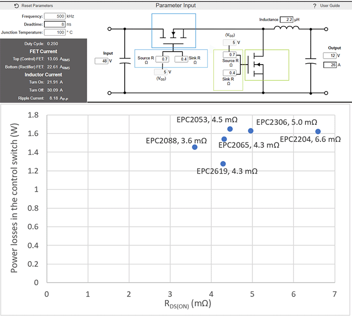 Figure 2 - Comparison of total losses in the control switch of a buck converter for devices with different RDS(ON)
To validate this selection, the applications group from EPC went ahead with a real-world side- by- side comparison of the ONSemi FDMS2D5N08C and the latest generation EPC2619. Two boards were built with identical sizes, and as close as possible layouts, as shown in Figure 3.
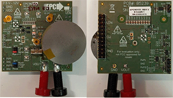
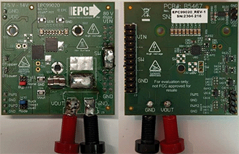 Figure 3 - Top and bottom view of test board for EPC2619 (left) and FDMS2D5N08C (right)
The results of the comparison are shown in Figure 4, and confirm the previous comparisons: the 3.3mO EPC2619 GaN FET has much lower losses than the 2.2mO FDMS2D5N08C Si MOSFET. Please note the measured results contain the inductor losses also (the same inductor was used for both boards).
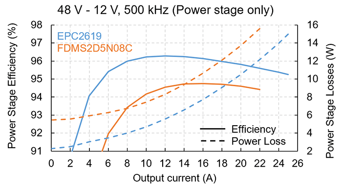 Figure 4 - Efficiency and losses from the operation in a 48V to 12V, 26 A buck converter operated at 500kHz
From a designer perspective, RDS(ON) is an easy way to compare devices; however, we have seen that it is a misleading indicator of actual performance. Moreover, although the trends we have seen are quite consistent, the exact tradeoffs are application and condition-specific, making them even harder to assess from a simple reading of the datasheet. That is why EPC has invested in tools like the silicon vs. eGan FETs cross reference tool and the buck loss calculation tool to quickly guide users to the right GaN FET. Hopefully, this will reduce the use of RDS(ON as a main criteria for device selection.
Understanding the limitations of traditional parameters like RDS(on) is crucial as power electronics technology continues to evolve. The cross-reference tool, provided by EPC and DiscoverEE, enables designers to navigate the transition from Si MOSFETs to GaN FETs, thereby maximizing the performance of their system.
Start optimizing your designs – try the cross-reference tool today.