Driving High-Efficiency Server Power with a 5 kW, 4-Level Totem-Pole PFC Converter
GaN Talk – Marco Palma
Oct 22, 2025
Introduction
As server and data center operators demand higher efficiency and greater power density, power supply designers are increasingly turning to gallium nitride (GaN) technology. GaN’s fast switching speeds, low losses, and compact device footprints enable system architectures that would be impractical with silicon.
The EPC91107KIT, shown in figure 1, is a 5 kW evaluation platform that demonstrates how 200 V EPC2304 GaN FETs can be leveraged in a 4-level totem-pole power factor correction (PFC) converter to achieve superior efficiency and compliance with Open Compute Project (OCP) standards. This blog explores the design philosophy, hardware, control strategy, and experimental performance of this solution — showing how GaN enables a new level of power density for data center power supplies.
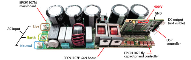 Figure 1: EPC91107KIT 5 kW, 4-level totem-pole PFC evaluation board
Why Multi-Level Totem-Pole PFC?
The totem-pole PFC is already the gold standard for high-efficiency AC–DC front ends in data centers. By moving beyond the traditional two-level design to a multi-level flying capacitor topology, engineers can further reduce switching losses, device stress, and input current distortion. The block diagram is shown in figure 2.
In the EPC91107, the four-level structure allows the required PFC inductance to be reduced from ~130 µH (two-level) to just 13.8 µH, enabling the use of compact, off-the-shelf inductors. This translates directly into higher power density and faster transient response.
 Figure 2: Block diagram of the multi-level PFC converter
Meeting the Open Rack V3 (ORV3) Challenge
The OCP’s Open Rack V3 (ORV3) specification places strict constraints on size: power supplies must fit within a 40 mm × 70 mm × 630 mm envelope. To achieve 5 kW within these dimensions, designers must carefully allocate space for:
- Bulk capacitors: Vertical, short capacitors reduce assembly complexity and meet electrical/mechanical requirements.
- EMI filter: Located in a “quiet zone” near the capacitors to minimize noise coupling.
- Converter stage: Positioned near the output, optimized for cooling paths.
Cooling is achieved via forced air through the length of the PSU or side-wall heat spreading, pushing large semiconductors to the board’s edge for thermal accessibility.
The EPC91107KIT comprises four modular boards:
- EPC91107M Motherboard: EMI filter, in-rush limiter, bulk capacitors, housekeeping power supply.
- EPC91107P GaN Power Board: Core 4-level totem-pole stage with EPC2304 FETs, isolated gate drivers, and measurement circuits.
- EPC91107F Flying Capacitor Board: Houses flying capacitors and provides controller interface.
- Microchip dsPIC Controller Card: Provides high-resolution PWM generation, PLL synchronization, and feedback control.
The GaN card, measuring just 92.5 mm × 38.5 mm, integrates the high- and low-frequency bridges and feedback circuits, minimizing PCB footprint.
 Figure 3: The EPC91107KIT comprises four modular assemblies for power, capacitors, and control
Control Strategy
The EPC91107 employs a traditional PFC control loop, adapted for the four-level architecture.
- A phase-locked loop (PLL) locks to grid frequency, generating a sinusoidal reference.
- An outer voltage loop calculates peak current reference using a zero-order hold (ZOH) function to minimize distortion.
- An inner current loop compares measured current against reference, with feed-forward scaling for dynamic response.
- Three complementary PWM channels, phase-shifted by 120°, drive the GaN devices symmetrically.
Notably, the flying capacitor voltages self-balance due to the continuous inductor current, eliminating the need for active balancing circuits.
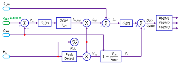 Figure 4: Control block diagram of the 4-level PFC, featuring PLL, voltage, and current loops
Thermal Considerations
The evaluation kit is supplied without a heatsink, relying on forced air cooling for initial evaluation. However, for higher load conditions, EPC recommends:
- Backside cooling with fans directed over the FETs.
- Heat-spreaders with TIMs (thermal interface materials) to improve heat conduction.
- EPC suggests t-Global TG-A1780 (17.8 W/m·K) TIM for device interfaces and TG-A620 (6.2 W/m·K) for heat-spreaders.
This hybrid approach balances electrical insulation, mechanical compliance, and thermal conductivity.
Experimental Validation
Testing of the EPC91107 confirms the design’s ability to meet — and exceed — industry standards:
- Efficiency: >98% from 60–100% load at 240 VAC input, 400 VDC output
- Input THD: <5% from 40–100% load, complying with OCP/M-CRPS requirements
- Power Factor: Near unity across load, exceeding ORV3 expectations
- Waveforms: Clean sinusoidal input current tracking input voltage at 5.18 kW confirms control accuracy
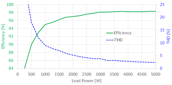 Figure 5: Efficiency exceeds 98% and iTHD remains below 5% across most load conditions
Relevance for Server Power
The EPC91107 was built to show what is possible in ORV3-compliant server power supplies. By combining GaN FETs, multi-level topologies, and careful thermal management, designers can:
- Shrink PFC inductors by 90% (130 µH → 13.8 µH).
- Reduce system volume and weight while meeting OCP compliance.
- Achieve Titanium-class efficiency with margin.
- Future-proof against evolving AI, HPC, and cloud infrastructure demands
 Figure 6: Measured efficiency operating with VIN = 230 VRMS, at both 50Hz and 60Hz, VOUT = 400 VDC, including housekeeping power.
Conclusion
The EPC91107KIT is more than an evaluation board — it’s a reference point for the future of server power design. By showcasing a 5 kW, four-level totem-pole PFC built on EPC2304 GaN FETs, it demonstrates how GaN enables unparalleled efficiency, density, and compliance with OCP standards.
For engineers designing the next generation of data center power supplies, the EPC91107 proves that GaN isn’t just an alternative to silicon — it’s the key to delivering smaller, faster, cooler, and more efficient systems.
Design Resources:
- Visit the EPC91107 product page to download schematics, BOM, quick start guides, and Gerber files
- Access EPC’s GaN First Time Right design resources for reference designs and application notes.
- Ask a GaN Expert and discuss how EPC’s GaN solutions can help meet your system efficiency and density goals.
Tags: