How to Design Wide Input Voltage Range and Optimized PCB Layout for GaN-based Motor Drives for High-Voltage Battery Applications
GaN Talk – Federico Unnia
Aug 09, 2025
Introduction
A motor drive inverter reference design featuring a wide input range from 30 V to 140 V is suitable for battery systems of 80 V, 110 V, and more.
Examples of applications include industrial automation systems, agricultural machinery, and material handling equipment such as forklifts. This
blog post discusses the design of an off-the-shelf reference design for these systems, with a focus on the PCB layout developed to optimize the
performance of the GaN FETs used.
150 V-rated Motor Drive Reference Design
The EPC91200 is a 150 V-rated, fully configured motor drive inverter board compatible with
DC bus voltages from 30 V up to 140 V. The design features the EPC2305, a 150 V-rated GaN FET,
with 2.2 mΩ typical ON-resistance. The reference design board is intended to be directly used on the wide variety of applications that use 80 V to
110 V batteries. The schematic principle of the board is shown in Figure 1.
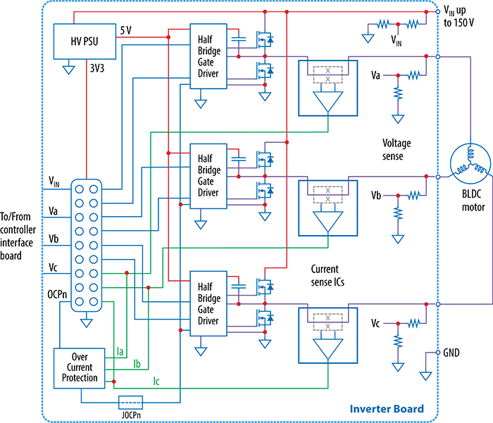 Figure 1: Block diagram of EPC91200
EPC2305 is pin-to-pin compatible with all EPC’s QFN discrete FETs, so it can also be assembled also for EPC2302
and EPC2304, 100 V and 200 V rated respectively or the reduced RDS(on) versions EPC2306,
EPC2308, EPC2307, rated respectively at 100 V,
150 V, 200 V. If FETs with different voltage rating were used, only the voltage dividers that measure the DC bus and phase voltage should be modified to
optimize the measurement range.
Design Features
Figure 2 shows the main features of the EPC91200 on the top side and bottom side respectively.
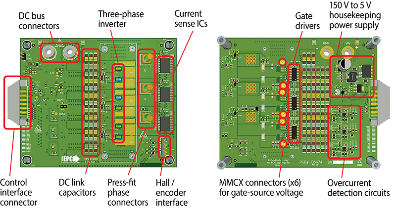 Figure 2: Top side of EPC91200 board
The phase current is measured through current sense ICs of the ACS37003-family. The low internal resistance (265 µΩ) of such components helps to reduce
the heating on the board and to minimize the losses on the inverter. Currently, the family only includes one device compatible with 3.3 V supply, which
is also the voltage supply of the microcontrollers that control EPC motor drive boards. However, EPC91200 can be assembled with 5 V supplied current
sense ICs of the same family since a conditioning circuit that converts the signals from the 5 V range to the 3.3 V range is present on the board.
A full bidirectional overcurrent protection circuit is triggered from any of the three phase currents to prevent unwanted failures. The positive and negative
overcurrent thresholds can be adjusted through resistors, and the time constant of the overcurrent signal is set through a RC filter connected to the
shutdown signal of the gate drivers.
The generation of the 5 V power supply is made through a circuit that uses power integrations LNK306, making it suitable for DC voltage ranges from 30 V to
150 V. The DC link capacitors are 100 V ceramic and are stacked to reach 150 V capabilities. Using two 100 V-rated stacked capacitors today yields a better
tradeoff than using 200 V-rated capacitors in terms of equivalent capacitance per area.
The EPC91200 is compatible with all EPC’s controller cards that interface with microcontroller boards from various manufacturers including ST Microelectronics,
Texas Instruments, Microchip and Renesas. The Field-Oriented-Control (FOC) firmware for all these controllers is available, and the connector J80 on the board
makes it possible to interface hall sensors or a quadrature encoder.
PCB Layout Approach
The PCB layout of EPC91200 has been optimized, focusing on the DC resistance between the input DC connectors and the phase connectors, since in motor drive
applications, the ON-resistance and the PCB resistance contribute significantly to the overall losses.
The Würth Redcube press-fit phase connectors used to connect the inverter to the motor make excellent ohmic contact. The male version of the connectors is
used to make the board ready for the use, as only bolts and washers are needed to connect the board to the motor cables.
Furthermore, the stackup of the board, shown in Figure 3, has been optimized to keep the heavier copper layers just below the top-layer: the first two
internal layers are indeed 4 oz. (140 µm) thick, allowing for most of the DC current and heat to spread. The two central layers have been used to route
most of the analog and digital signals. The remaining layers are the mirror of the first three to maintain symmetry.
Additionally, a finite element analysis tool integrated with the PCB editor has been used to analyze both current density distribution and DC trace
resistance to verify the effect of using heavier copper layers below the GaN FETs.
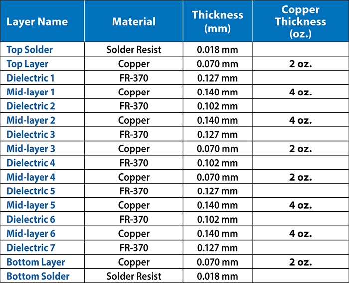 Figure 3: Stackup of EPC91200
Unlike DC-DC GaN applications, which necessitate HF loop decoupling capacitors on the same side of the GaN FETs and additional middle-frequency capacitors on
the opposite side due to fast transitions on the switching node, motor drive inverters have slower transitions. Consequently, the number of decoupling capacitors
can be reduced and relocated to the opposite side of the PCB. This adjustment makes more room for copper planes on the side of the FETs, aiding in the dispersion
of heat generated by the FETs and minimizing copper resistance.
Conclusion
In conclusion, the EPC91200 motor drive inverter reference design offers a versatile solution for a wide range of applications, including those utilizing battery
systems with voltages such as 80 V and 110 V. The board is a general-purpose motor drive inverter, it can be used either with field-oriented-control techniques
or can be interfaced with sensors, it has a bidirectional overcurrent protection on each leg with the possibility of adjusting the thresholds. The optimization
of the PCB layout to minimize the resistive losses due to the PCB DC resistance have been verified using a finite element analysis tool integrated with the PCB CAD.
By leveraging the benefits of GaN FET technology and PCB design considerations, the EPC91200 demonstrates efficiency, reliability, and adaptability for diverse
motor drive applications. With its wide input voltage range and layout optimization, the EPC91200 offers an off-the-shelf solution for engineers designing
high-performance motor drive systems.
More Information:
- Visit the EPC91200 landing page to access the design files and get started on your motor drive innovations today!
- Ask a GaN Expert how GaN FET technology can take your designs to the next level.